What is PIC16F887?

Sarah Cherry
Published Mar 17, 2026
What is PIC16F887?
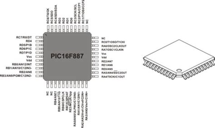
The PIC16F887 is an 8-bit microcontroller from Microchip. The 40-pin IC has 14 Channel 10-bit ADC making it suitable for applications which require more ADC inputs. The IC also has 2 Comparators, 2 Timers (8-bit and 16-bit) and supports SPI, I2C and UART communication protocols.
How is PWM defined?
Pulse width modulation (PWM) is a modulation technique that generates variable-width pulses to represent the amplitude of an analog input signal. The output switching transistor is on more of the time for a high-amplitude signal and off more of the time for a low-amplitude signal.
What is PWM in microcontroller?
Pulse Width Modulation (PWM) is a technique where the width of digital pulses is adjusted to generate different average dc voltages. Most microcontrollers have a built-in timer that can be used to generate a PWM signal.
What is PWM in pic16f877a?
Pulse-width modulation (PWM) is a modulation process or technique used in most communication systems. The PWM signal we can use to control the speed of DC motor or to control the intensity. These signals may also be used for approximate time-varying of analog signals. …
How many bit microcontroller is PIC16F877A?
8-bit
PIC16F877A is a powerful easy-to-program , CMOS FLASH-based 8-bit microcontroller packs Microchip’s powerful PIC® architecture into an 40- or 44-pin package.It has 256 Bytes EEPROM data memory,self programming and 2 nos of PWM.
Why do we use PWM?
Pulse width modulation is a great method of controlling the amount of power delivered to a load without dissipating any wasted power. The above circuit can also be used to control the speed of a fan or to dim the brightness of DC lamps or LED’s. If you need to control it, then use Pulse Width Modulation to do it.
Which port of the pic16f887 is used to generate PWM signal using PWM1 output?
PIC16F877A PWM Module
| PWM Channel | Port Pin | Period Register |
|---|---|---|
| PWM1 | PC.2 | PR2 |
| PWM2 | PC.1 | PR2 |
What is PWM in PIC?
PIC PWM for the PIC Microcontroller. This page shows you how to setup registers in PIC microcotnrollers to control the PWM module. Pulse width modulation or PWM is simply the creation of a digital signal that is turned on and off at a repeated rate (specific period) and with a varying mark to space ratio.
What are the features of the pic16f887?
The PIC16F887 incorporates 256 bytes of EEPROM data memory, 368 bytes of RAM, and program memory of 8K. Apart from self-programming capability, it also contains 2 Comparators,10-bit Analog-to-Digital (A/D) converter with 14 channels, and capture, compare and PWM functions.
What is the use of pull up resistor in pic16f887?
Digital Input: There are multiple input pins on the microcontroller and all of them come with an input pull-up resistor. In PIC16F887 the number of input pins is larger from all other pins and they can be used to wake up the microcontroller in case of sleep.
How many locations of ROM does the pic16f887 have?
The PIC16F887 has 8Kb of ROM (in total of 8192 locations). Since the ROM memory is made with FLASH technology, its contents can be changed by providing a special programming voltage (13V).
What are the ADC channels of pic16f887?
All ADC channels of PIC16F887 are given below: In PIC16F887 there are three timers (Timer0, Timer1, Timer2), two of them are 8-bits and the last one is a 16-bit timer. All these timers can use both external and internal oscillator but timer1 can use a third oscillator at some GPIO pins.