How does a CAN bus system work

Christopher Anderson
Published Apr 15, 2026
The CAN bus system enables each ECU to communicate with all other ECUs – without complex dedicated wiring. … The broadcasted data is accepted by all other ECUs on the CAN network – and each ECU can then check the data and decide whether to receive or ignore it.
How does the CAN bus system work?
The CAN bus system enables each ECU to communicate with all other ECUs – without complex dedicated wiring. … The broadcasted data is accepted by all other ECUs on the CAN network – and each ECU can then check the data and decide whether to receive or ignore it.
CAN bus wiring explain?
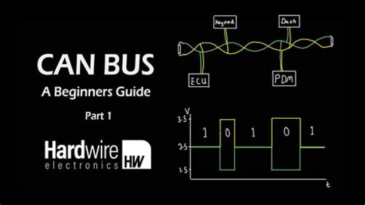
CAN bus uses two dedicated wires for communication. The wires are called CAN high and CAN low. When the CAN bus is in idle mode, both lines carry 2.5V. When data bits are being transmitted, the CAN high line goes to 3.75V and the CAN low drops to 1.25V, thereby generating a 2.5V differential between the lines.
CAN bus system basics?
A CAN-Bus message holds all kind of data, but the basics are an ID and a message frame (8 bytes). … A wagon (ID) has 8 private rooms (bytes) with each 8 seats (bits). Each seat (bit) can have a value of 0 or 1. A complete private room with 8 seats can have 256 different combinations, which is the maximum value of 1 byte.How is CAN bus powered?
A CAN implementation consists of multiple transceiver modules linked by a pair of bus wires. … To be compliant with the ISO standard and to provide the proper bus level, most CAN transceiver bus drivers should be powered by a 5V supply rail.
CAN bus terminating resistor?
A CAN Bus network must have a terminating resistor between CAN High and CAN Low for it to work correctly. … The resistance should ideally be less than 120 Ohms and closer to 60 Ohms if a resistor is fitted at each end of the bus.
How do you diagnose a CAN bus system?
- Unplug the connector from the device.
- Measure resistance on the connector pins of the device between CAN HI and CAN LOW. …
- Measure resistance between CAN HI and GROUND. …
- Measure resistance between CAN LOW and GROUND.
CAN bus wires twisted?
The wires are twisted because the signals transmitted on the wires are made from measurements on both wires, therefore when the wires are twisted together they are both subject to the same interference and the chance of discrepancy is greatly reduced. Most commonly the wires are green and white or green and blue.CAN bus voltage?
StateCAN High voltageCAN Low voltageRecessive2.5 volts2.5 voltsDominant3.5 volts1.5 volts
CAN bus system cars?CAN bus is a set of 2 electrical wires (CAN_Low & CAN_High) in the car network where information can be sent to and from ECUs. The network inside the car that allows ECUs to communicate with each other is called CAN (Controller Area Network). … Every ECU with it’s CAN controller and CAN Transceiver is called a node.
Article first time published onCAN bus data cables?
CAN-Bus Data Cable reduces wiring, electronic interference, and offers high-speed network communication. It is resistant to abrasions and cuts, while also has an excellent resistance to oil and chemicals. … The SAE J1939/15 is unshielded with no drain and the SAE J1939/11 CAN-Bus Cable is shielded with drain wire.
What powers CAN bus?
Most high voltage tolerant CAN bus transceivers can operate only from a 5V supply, but 5V is rarely used by most modern digital circuits. The CAN bus transceiver may be the only 5V component in the system.
CAN bus electrical specification?
Field nameLength (bits)PurposeACK delimiter1Must be recessive (1)End-of-frame (EOF)7Must be recessive (1)
CAN bus over power?
The DCAN500 device for CAN-BUS communication over noisy power lines (DC-CAN), supports CAN A/B protocols at speed up 500kbit/s. Multiple CAN networks may share a common DC or AC powerline where each network uses a different carrier frequency. The device avoids complex cabling, saves weight, and simplifies installation.
CAN bus failure modes?
Bus Failure Modes CAN_H shorted to battery voltage. CAN_L shorted to ground. CAN_H shorted to ground. CAN_L shorted to battery voltage.
CAN bus circuit malfunction?
CANBUS is a high speed network which requires high quality wiring in order to operate properly. As such, it is sensitive to improper wiring. The majority of CANBUS communication problems are caused by poor wiring, incorrect termination, or the use of multiple frequencies on the same bus.
CAN bus fault signal lost?
The failure of communication on the CAN bus can be caused by several sources: Failure of the CAN bus wiring inside the harness. Failure of one of the components or control units linked to the CAN bus. Failure of the voltage supply or ground to individual components or control units.
CAN bus shorted together?
Shorts and opens: The CAN controllers will tolerate a short circuit of one of the two lines to ground because of the characteristics of the differential bus. It cannot tol- erate both CAN bus wires shorted to ground or to each other. It will tolerate one of the CAN lines being open or disconnected.
CAN bus switchable termination?
The CAN bus may connect two or hundreds of nodes. … Switchable termination allows software configuration of termination locations when the CAN bus is changed. Using switchable termination, each board can be used for any node along the signal path simply by modifying the software.
Does CAN bus need a ground?
Yes, a common ground is need. A can transceiver has a maximum common mode voltage. If the common mode voltage of the differential CAN signals exceeds the maximum, then the transceiver will not be able to recognize the bits.
CAN bus noise?
Therefore the CAN bus transmissions lines are immune to any ground noise typically present in automotive applications. The signals on the two CAN lines will both be subject to the same electromagnetic filed level. … Reflections are bad because they can cause destructive interference that can corrupt any transmitted data.
CAN bus protocol?
The CAN communication protocol is a carrier-sense, multiple-access protocol with collision detection and arbitration on message priority (CSMA/CD+AMP). CSMA means that each node on a bus must wait for a prescribed period of inactivity before attempting to send a message.
Can Bus OBD2?
CAN is a method for communication (like a phone). In particular, the OBD2 standard specifies the OBD2 connector, incl. a set of five protocols that it can run on (see below). Further, since 2008, CAN bus (ISO 15765) has been the mandatory protocol for OBD2 in all cars sold in the US.
CAN bus data frame?
The data frame is the standard CAN message, broadcasting data from the transmitter to the other nodes on the bus. A remote frame is broadcast by a transmitter to request data from a specific node. An error frame may be transmitted by any node that detects a bus error.
CAN bus system advantages?
Integrated CAN bus communication offers a number of advantages for industrial PC users, including: Speed – CAN data transfer speeds far outstrip traditional analog wiring harnesses since multiple messages can be sent simultaneously to all connected devices, sensors or actuators.
CAN bus wiring Colours?
- Red is Power – 12 V.
- Black is Ground – 0 V.
- Yellow is CAN High – 2.5 V.
- Green is CAN Low – 2.5 V.
CAN Bus cable Automotive?
The CAN bus is a common digital data network used in automotive, industrial, medical and scientific systems. The CAN bus is used for routing sensor data between pieces of equipment. The main advantages are high resilience to noise, reliability, low cost, simple wiring and ease of use.
CAN Bus interface?
The CAN Bus interface uses an asynchronous transmission scheme controlled by start and stop bits at the beginning and end of each character. This interface is used, employing serial binary interchange. Information is passed from transmitters to receivers in a data frame.
CAN Bus 3 wires?
The CAN-bus uses 3 wires (CANH, CANL, GND) for communication between nodes. The CANH and CANL signal form a differential signal pair. Differential signals are much more immune against external influences such as high voltage wiring, inductive loads, …
Why 120 ohm is used in can?
Terminal resistors are needed in CAN bus systems because CAN communication flows are two-way. The termination at each end absorbs the CAN signal energy, ensuring that this is not reflected from the cable ends. … Hence 120 Ohm termination adaptors are considered the standard for CAN bus.
Can explained?
Originally invented by Bosch and later codified into the ISO11898-1 standard, CAN defines the data link and physical layer of the Open Systems Interconnection (OSI) model, providing a low-level networking solution for high-speed in-vehicle communications.